Hardware overview
The TPB.V1 Tube Preamp Buffer (the “Buffer”) internals are composed of the following 3 subassemblies:
- The power supply board (see left side of pic below)
- The tube board (see right side pic below)
- The rear panel (see center of pic below)
There is also a plastic spacer board required by the power supply board to hold the power supply board firmly in place.
The 2 boards slide into and out the enclosure via slotted grooves which hold the boards in place. The tube board is the top most board and goes into the 3rd set of slotted grooves down from the top. The power supply board goes into the bottom most slotted groove.
The entire buffer assembly is accessed and removed from the enclosure by withdrawing/sliding the entire assembly out from the rear of the preamp at the same time. Putting the assembly back into the enclosure is essentially the reverse of removing it.
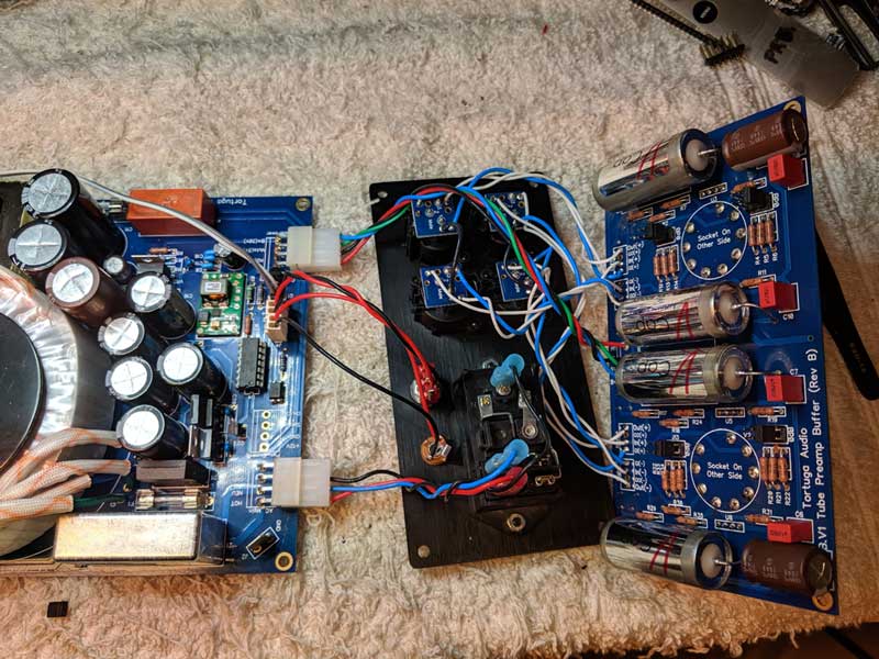
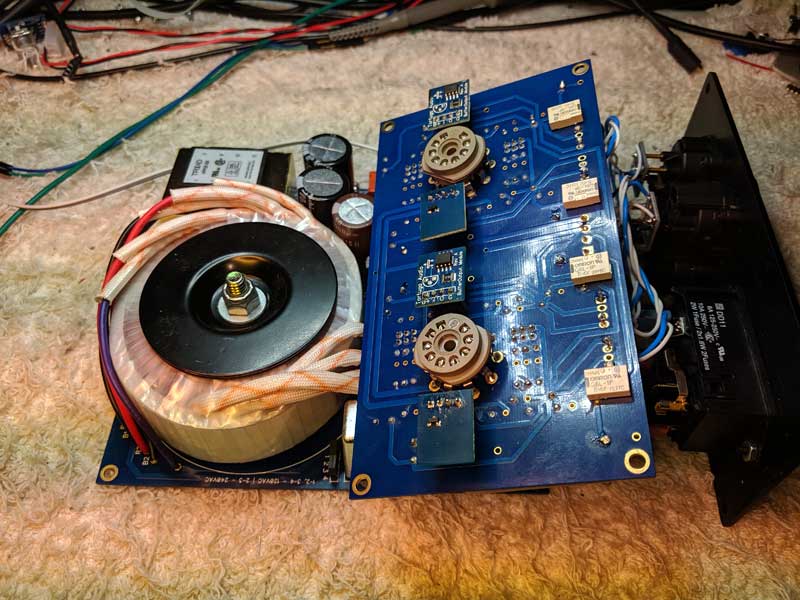
The removed assembly is shown in the 2 images below. The first shows all 3 subassemblies unfolded yet connected together. The second image shows the tube buffer assembly oriented as it will be as it’s inserted into the enclosure box.
These 3 subassemblies must be connected together prior to insertion into the enclosure box. The front panel will have already been attached to the front of the enclosure box.
Removal of buffer internal assembly
We recommend the following procedure:
- Remove the 4 socket head screws from the corners of the rear panel.
- Remove the single socket head screw located between the 2 tube holes in the top side of the enclosure.
- Grasp the rear panel and gently pull/slide the rear panel and attached boards out of the enclosure. Stop after the assembly has been pulled out roughly 3 inches.
- Turn the entire enclosure on to its side with the bottom of the enclosure facing you and the partially removed rear panel/assembly located to your left.
- Find the 2 inch wide spacer board that had been in the same bottom slot as the power supply board. Set the spacer board aside for now.
- Turn the entire enclosure over on its other side with the top of the enclosure facing you and the partially removed rear panel/assembly located to your left.
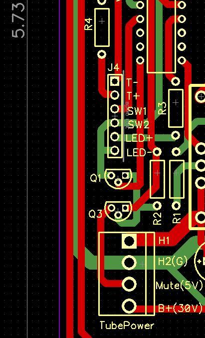
- While gently tilting the bottom edge of the rear panel back to left to better see the power supply board observe the series of small wires plugged into the pins of the power supply board (ignore the heavier white plastic connectors. Find the 2 wires plugged into the 2 right most pins of the power supply board pin header J4 as shown in the layout diagram below. The pins are labeled J4.LED+ and J4.LED-. These 2 wires run back into the enclosure towards the front and attach to the blue LED located in the front panel. Carefully note which colored wire goes into which pin. Gently remove the 2 wires from the 2 right most pins but pulling them by their square ends. Leave those 2 wires disconnected.
- Continue to gently pull the rear panel/buffer assembly out of the enclosure. At some point the tube board will be completely removed from its slots. Gently fold the tube board up and to the left such that it is now to the left of the rear panel making it easy to view the power supply board which is still partially inserted in the slotted enclosure.
- If you wish you can now turn the entire assembly and enclosure back so that its now laying with its bottom down as it would normally. You should be able to clearly see the first few inches or so of the power supply board at this point.
- Further withdraw the power supply board/assembly until approximately half of the large round toroidal transformer is now outside of the enclosure. Stop withdrawing the buffer assembly. You don’t have to fully remove the power supply board for most maintenance activities but you can if you like.
Buffer assembly insertion sequence
The entire buffer assembly is inserted through the rear end of the enclosure box according to the insertion sequence described below. Removing the buffer assembly is essentially this same sequence but in reverse.
- The power supply board is inserted first with the transformer end of the board going in first.
- Prior to inserting the power supply board, find the 12″ long 2-wire LED cable that’s connected to the LED in the front panel and make sure this cable remains clear of the power supply board as the board is inserted. Don’t let this cable disappear into the enclosure box as the power supply board is inserted because this cable will need to be attached to the J4.LED+ and J4.LED- of the power supply board once the board is almost fully inserted.
- The power supply board occupies the lowest slot in the enclosure box. Make sure the board is going into the bottom most slot. It should slide in relatively easily but may bind occasionally.
- Once the power supply board is approximately 80% inserted into the enclosure box, attach the LED cable to the J4.LED+ and J4.LED- pins on the J4 header which is located on the opposite end of board from the transformer end.
- Gently continue to push the power supply board into the enclosure but not yet all the way towards the front panel.
- Before the power supply board can be pushed all the way in where it stops against the front panel, the tube board must also be inserted.
- The tube board occupies the 3rd slot from the top of the enclosure box.
- The tube board is oriented and inserted with the tube sockets facing up as shown in the image above.
- As the tube board slides forward in the 3rd slot, also nudge the power supply board forward towards the front panel.
- Push both of these boards into the enclosure until the power supply board is up against the front panel and can’t go in any further and until the tube board is far enough in where the tube sockets are aligned with holes in the top of the enclosure box.
- Insert the 2″ blank spacer board into the same bottom slot as the power supply board until the spacer board is flush up against the power supply board.
- Gently push the power, control and audio signal wiring into the space between the tube board and the power supply board as you push the read panel into place against the end of the enclosure box.
- Install the 4 socket head screws with washers into the 4 corners of the rear panel. DO NOT OVER-TIGHTEN the rear panel socket head screws or they will shear off.
Setting The Mains Voltage
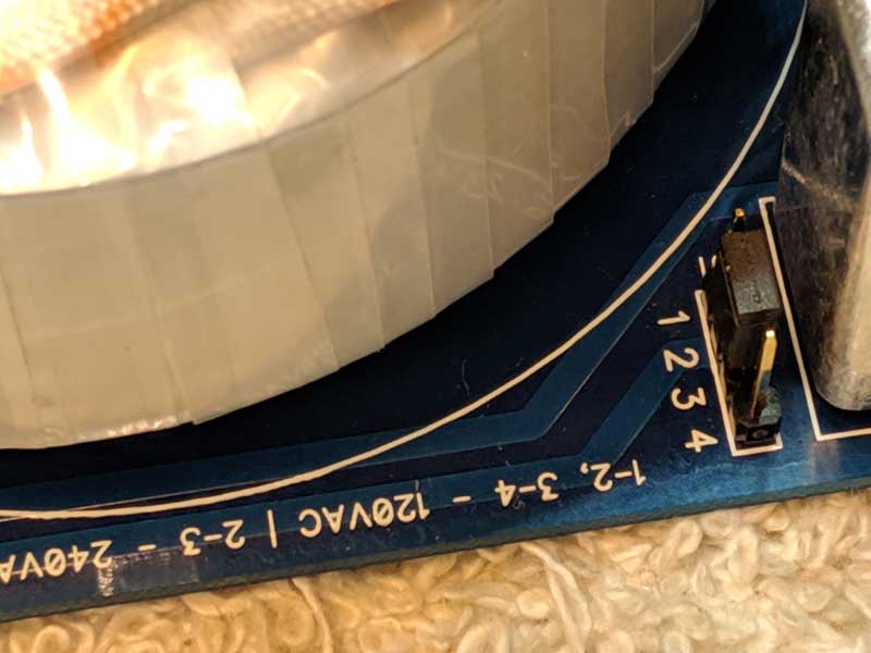
The tube buffer can operate on either US 120VAC or International 240 VAC mains power. The mains voltage is determined by setting jumpers on J1, a 4 pin header that is inconveniently located between the transformer and the AC input filter on the power supply board as shown in the image below.
The mains voltage level is determined by jumpers (shunts) on the pins of J1 as follows:
- 120 VAC | place one jumper across J1 pins 1 and 2, and a second jumper across J1 pins 3 and 4
- 240VAC | place one jumper across J1 pins 2 and 3
The image below shows only 1 jumper placed across pins 2 and 3 indicating that this power supply is configured for 240 VAC mains power.
In order to access the J1 pin header, the buffer assembly will have to be almost fully removed from the enclosure box. The power supply board will have to be withdrawn sufficiently far out of the enclosure box to expose the J1 pin header shown in the image above.
Replacing Fuses
The Buffer has 3 separate fuses. All fuses are standard 5 x 20 mm size.
The mains fuse is located in a drawer that is part of the IEC power input with integral switch located externally on the left side of the rear panel. This mains fuse is rated at 3 amps.
There are 2 internal fuses, F1 and F2.
F1 is the tube heater fuse. It’s located immediately next to the Z1 mains filter as shown in the diagram above. The F1 fuse is rated at 2.5 amps.
F2 is the plate/auxiliary power fuse. It’s located on the opposite side of the power supply board from the J1 mains voltage header. The F2 fuse is rated at 200 milliamps (0.2 amps). In more recent builds this fuse has been jumpered and abandoned due to it being deemed redundant.
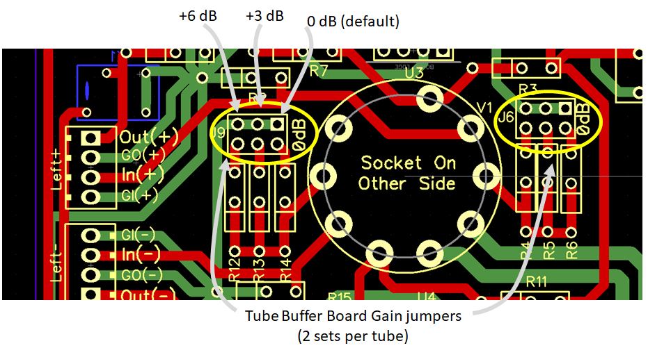
Changing The Gain
The gain setting can be changed by changing the gain setting jumper position on the buffer’s Tube Board as shown in the circuit board layout shown below.
The TPB.V1 usually ships with its gain set at the default 0 dB setting. There are 2 additional optional gain settings; +3 dB and +6 dB.
Please note that there are 4 separate sets of gain jumpers with only 2 sets shown in the image below. For single-ended buffers only one set of gain jumpers will be present adjacent to each tube (2 total jumper sets). For balanced buffers, there will be 2 sets of gain jumpers adjacent to each tube (4 total jumper sets). Jumpers must be set the same on all sets of jumpers.