3 pin XLR wiring
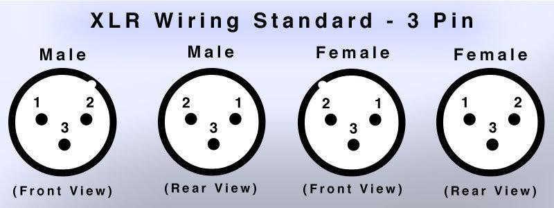
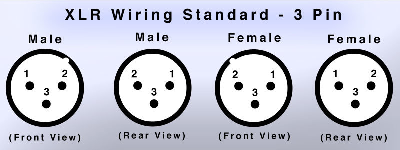
Balanced audio signals typically use XLR type 3-pin connections. XLR wiring is unavoidably more complex than single-ended RCA.
First, you are dealing with three (3) terminations per channel; two signals (pin 2 and pin 3) plus one shield/ground (pin 1). Next, you have both male (output) and female (input) type connectors each of which reverse the position of pins 1 and 2 with respect to the other while pin 3 remains thankfully unchanged. Last, but not least, some diagrams show the pins in a front view while another may use a rear view.
For purposes of your sanity and this guide, assume all XLR connectors herein are rear view only.
V25 balanced audio wiring
Connecting balanced audio signals and ground to the V25 can be challenging for the simple reason that it’s a bit complex and thus it’s easy to make a mistake.
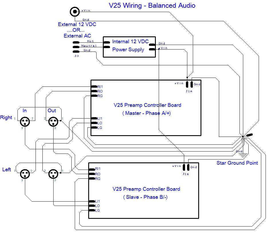
The correct way to wire balanced audio to the V25 is shown below in two different diagrams below. The first is a more abstract schematic representation while the second looks closer to actual wiring to the boards. In either diagram we only terminating a single input and a single output to the left and right channels.
Before diving in with wiring your V25 boards, we strongly recommend you study these diagrams until you understand the wiring scheme represented here. The wiring scheme is summarized in the following bullet points:
- Master board handles the A/+ phase of both the right and left channels
- Slave board handles the B/- phase of both the right and left channels
- All grounds (including the pin 1’s) get wired to a single common “star ground” point somewhere within the enclosure
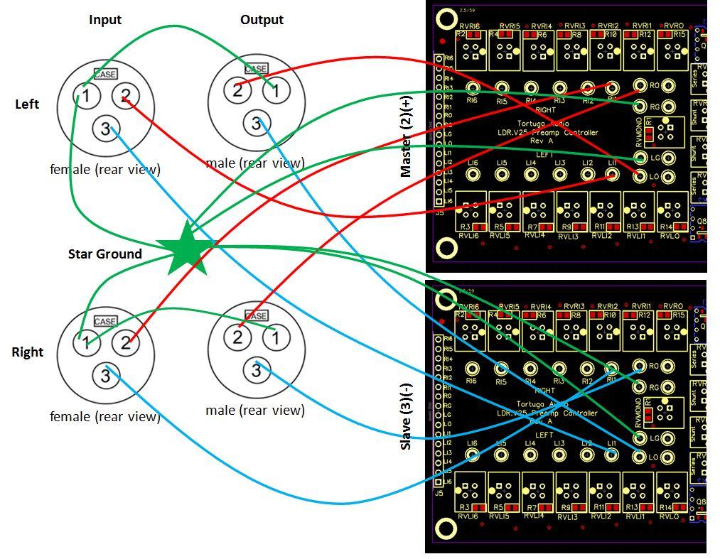
 The wiring diagram shown below is consistent with the schematic shown above and is provided to show where the wires need to be connected on the actual V25 boards. Note that this is only for a single input so the input is connected to the solder pads labeled RI1 and LI1 on each board. For additional inputs you would terminate the wires to solder pads RI2 and LI2 etc.
Alternatively you could also make the same terminations via the J5 pin header or some combination of the J5 header and the solder pads.
Lastly, 2 solder pads are provided on the V25 board for both the output (RO and LO) and the signal ground (RG and LG). This is simply for convenience.